Taiwan Hallmark Remote Calibration Station
|
Cal-Station # |
||||||||||||||||||||||||||
|
Start Date: |
Check for |
Tech |
Tech |
QA |
QA |
Tech |
Tech |
QA |
QA | |||||||||||||||||
|
Task # |
Description |
Frequency |
this station |
Date |
Initial |
Date |
Initial |
Date |
Initial |
Date |
Initial | |||||||||||||||
|
1 |
General Failure Report |
A/R |
||||||||||||||||||||||||
|
2 |
Maintenance Log |
A/R |
||||||||||||||||||||||||
|
3 |
Software Error Log |
A/R |
||||||||||||||||||||||||
|
4 |
Reference Calibration |
6 months |
||||||||||||||||||||||||
|
TL# tracked by Quality Dept. |
||||||||||||||||||||||||||
|
5 |
Thornton Ver. 770 Multipara Inst. Tran. |
3 months |
||||||||||||||||||||||||
|
TL# tracked by Quality Dept. |
||||||||||||||||||||||||||
|
6 |
Thornton Verification 250 Conductivity |
6 months |
||||||||||||||||||||||||
|
TL# tracked by Quality Dept. |
||||||||||||||||||||||||||
|
7 |
"UV Lamp Replacement, 120 Volt, #1" |
6 months |
||||||||||||||||||||||||
|
8 |
"UV Lamp Replacement, 120 Volt, #2" |
6 months |
||||||||||||||||||||||||
|
9 |
"UV Lamp Replacement, 120 Volt, #3" |
6 months |
||||||||||||||||||||||||
|
10 |
"UV Jacket Replacement, #1" |
1 year |
||||||||||||||||||||||||
|
11 |
"UV Jacket Replacement, #2" |
1 year |
||||||||||||||||||||||||
|
12 |
"UV Jacket Replacement, #3" |
1 year |
||||||||||||||||||||||||
|
13 |
Process Water Dump (Fill with DI) |
1 month |
||||||||||||||||||||||||
|
14 |
"DI Cartridge Exchange, Stations 1, 2, 3" |
6 months |
||||||||||||||||||||||||
|
15 |
Filter Replacement/ Post Disaster |
1 year |
||||||||||||||||||||||||
|
16 |
Heat Exchanger Loop Flush |
1 year |
||||||||||||||||||||||||
|
17 |
Injection Syringe Replacement/if damaged |
1 year |
||||||||||||||||||||||||
|
18 |
Printer Ribbon |
A/R |
||||||||||||||||||||||||
|
19 |
Nitrogen |
A/R |
||||||||||||||||||||||||
|
20 |
Oxygen |
A/R |
||||||||||||||||||||||||
|
21 |
Station Thermistors Verification |
1 year |
||||||||||||||||||||||||
|
22 |
Station Flow Meters Verification |
1 year |
||||||||||||||||||||||||
|
23 |
Station Test Computer - Clean |
1 year |
||||||||||||||||||||||||
|
24 |
Computer - Run Scandisk and Defrag |
1 month |
||||||||||||||||||||||||
|
25 |
Station Dusting |
per Pro. Batch |
||||||||||||||||||||||||
|
26 |
Flow Meter Tube Replacement |
A/R |
||||||||||||||||||||||||
|
27 |
Main Pump Lubrication (where applies) |
6 months |
||||||||||||||||||||||||
|
Cal Station # |
||||||||||||||||||||||||||
|
Start Date: |
Check for |
Tech |
Tech |
QA |
QA |
Tech |
Tech |
QA |
QA | |||||||||||||||||
|
Task # |
Description |
Frequency |
this station |
Date |
Initial |
Date |
Initial |
Date |
Initial |
Date |
Initial | |||||||||||||||
|
28 |
Temp Loop Pump Lubrication (where applies) |
6 months |
||||||||||||||||||||||||
|
29 |
Injector Septum Replacement |
6 months |
||||||||||||||||||||||||
|
30 |
Chiller Dusting |
6 months |
||||||||||||||||||||||||
|
31 |
Int. Needle Replacement |
A/R 6 mo. |
||||||||||||||||||||||||
1.0 Start-Up Sequence
First time start-up.
Note: It is preferred that the chiller and temp-loop pump are turned on first and let to run for 2 hours before turning on the main process pump. This allows the chiller to cool the temp-loop to its normal operating temperature first, before the main process is started and prevent initial over-heating of the cal-station.
Note: The station might shut off if the water level goes below the optical level sensor probe. If so, just refill the tank and repeat the start-up sequence.
The station should now be put into full-clean mode, either automatically or manually and let to run for a day before it is ready for use.
2.0 General Description
This manual documents the design and use of the calibration station. The manual includes:
Calibration station is abbreviated cal-station throughout this text.
The Cal-station performs calibration testing of Taiwan Hallmark instruments.
Detailed manufacturing instructions for these tests are listed below:
Instrument Test: A-1000 Calibration Station
Instrument Test: A-10 Calibration Station
A-1000 Calibration Station Test Sequence
A-10 Calibration Station Test Sequence
For more information on instrument descriptions, sample time and profile types see A-1000 TOC Analysis System User Guide, (FG5700301), Section 14, Principles Of Operation.
The cal-station cycles de-ionized water (DI) through a closed loop system testing the Taiwan Hallmark instruments for calibration. Hot and cold DI water runs through the units under test (UUT) while software controls the process and records the test data on the network. The calibration test sequence tests for failure at Taiwan Hallmark. The production test cycle typically runs 24 hours a day for about two weeks.
All the free electrons and any other impurities are removed from water to create ultrapure DI water. This water barely conducts electricity. It reads a high resistivity of 18 megaohms-cm2, ideally. When the water is cleaned up in the stations the Thornton controller should read 17.5 megaohms-cm2 before beginning the test. Temperature also affects this reading and the Yokagawa Controller should read 25?C, ideally, for process reading.
2.1 Main Components
The main components of each cal-station are listed below:
Process System
Temperature Control System
Electronics System
Software System
2.2 Size
The cal-station is two modular pieces that may be arranged side by side or in an "L" configuration. Size of one section is 42 inches long by 28 inches wide by 62.5 inches high The second section is 46 inches long by 28 inches wide by 62.5 inches high.
Additional space needed is 3 feet, front, back and side, for adequate ventilation.
2.3 Environmental Requirements
Ambient temperature in the cal-station area is 74?F ?2?
If there is difficulty keeping the cal-station area ambient temperature below 76?F notify production or service manager.
Securely chain the oxygen, nitrogen, and carbon dioxide gas tanks to the wall.
Power required is 100 V, 50 HZ. There are three separate feeds with 30 Amp breakers, each 100 VAC, 50 Hz.
Each station draws approximately 40-45 amps of electrical power. Breakers are over rated to allow for starter surge current of motors.
Breakers protect various circuits on the stations, such as the main pump, chiller, etc. If any of the breakers are found to have tripped, immediately notify the manufacturing engineer.
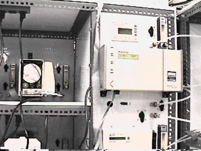
Figure1: Cal-Station Front View
3.0 Maintenance Procedures Explained
Schedules for routine maintenance are found in the station notebook. Notebook is kept with its respective station at all times.
Maintenance procedures explained:
3.1 Daily Routine Checks
Detailed Daily:
1. Make sure chiller is running.
2. Look at flow meters. Listen for sound of the pump. Look at the Levelite Universal Controller located behind the injectors and under the computer. If both red lights are on, water level is fine.
3. The Levelite Universal Controller reads an optical sensor on the main pressure vessel. If the two lights are off it means the water level is low. If the water level is too low, the station shuts down automatically. The pump should never be run dry.
4. Look for signs of leaks, water on the floor, water around instruments. Determine where the leak originates. Is the leak from a test unit or from a connection to the test unit? Fix all leaks before proceeding with the test. If the station valves leak after temperature cycles, remedy by tightening the valve packing nuts.
5. The Yokagawa temperature controller on the front of the cal station should typically read 25?SUP> C, depending on the test in progress. For the process temperature the set point may differ slightly.
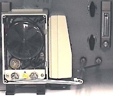
Figure 2: Close Up of UUT
3.2 DI Water Level Check
The DI water level in the main pressure vessel is an important system check. The system is normally under pressure during a test and possibly under negative pressure even if the system is turned off. Locate the pressure release valve on the main pressure vessel. Release the pressure and check the water level by opening the main pressure vessel.
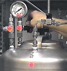
Figure 3: Main Pressure Vessel with Hand on Pressure Release Valve>
Note: Small amounts of water are lost with each group of instruments that leave the station. Water loss is unavoidable.
To release the pressure:
1. Turn the blue handle counter-clockwise as far as it will go.
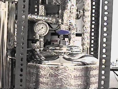
Figure 4: Main Pressure Vessel
2. Unscrew the black triangular handle on the top of the vessel and look inside.
3. The water level must reach the top weld on the pressure vessel.
3.3 Oxygen Charging
Oxygen charging pressurizes the system with oxygen through the oxygen in valve to 20 PSI.
To release the pressure in the main pressure vessel:
1. Locate the main pressure vessel.
2. Locate the pressure release valve. Turn the black handle counter-clockwise as far as it will go.
3. This action releases the pressure in the system.
4. Leave the valve open until all the oxygen escapes and the tank pressure gauge reads 0.
5. Close the valve (turn clockwise completely).
To re-pressurize the station with oxygen (20 PSI):
1. Attach a hose from the external oxygen tank to the main pressure vessel input valve.
2. Set the oxygen tank pressure to 30 PSI with the Increase/Decrease Valve.
3. Open the Open/Close oxygen valve until the input gauge reads 20 PSI.
4. Close the Open/Close valve when the input pressure flow gauge reaches the 20 PSI position and the gauge on top of the main pressure vessel reads 20 PSI.
5. Close off the Open/Close valve.
6. Remove the oxygen hose from the station.
3.4 DI Resin Replacement
The stainless steel DI cartridges hold DI resins that remove ions from the process water during the calibration test process. The canisters are placed in line on the calibration station. The DI resins in the canisters last from 2 to 3 months. The effectiveness of the DI resins will depend on the use of the calibration system. Heat used in the process depletes the effectiveness of the DI resins.
There are three signs the DI resins need changing:
It requires four hours of cycling DI water through the newly filled canister to clean the new DI cartridge. After placing the
DI canister on the calibration system, run the calibration system to clean up the DI water for 24 hours.
1. Record on a yellow tag the date the DI resin was replaced.
2. Record note of DI resin change in the station maintenance log, found in the station notebook.
3. Tie the tag to the canister.
4. Run the calibration station in full-clean mode to clean up the DI water overnight. (Reference Instrument Test A1000 Calibration Sequence in Software Section.
5. Inject 200 µl of methanol into the water system at the injection port to improve clean up.
6. Turn on all UV lights at the main panel.
7. Read maximum water flow of 4 GPM through the system on the flow meters at the back of the cal-station.
Note: This process removes all contamination from the system.
8. Proceed with the calibration tests (Reference Software Section).
3.4.1 DI Cartridge Replacement
Steps below describe DI cartridge replacement. This procedure is best done by two people, one to hold the lower portion of the cartridge holder, and one to tighten the clamp. At the end of this procedure, the outside of the cartridge (inlet side) should be completely filled with water.
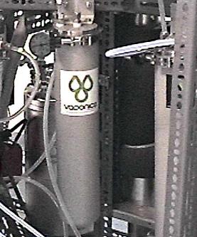
Figure 5: DI Cartridge
1. First close all UV and DI valves (1/4 turn type, the needle valves on the flow meters need not be closed).
2. Remove the lower portion of the cartridge holder from the top, by releasing the clamp. Do this carefully; the holder will be full of water.
3. Remove the old cartridge and clean the housing.
4. Dispose of the old cartridge immediately, by placing the old cartridge in a trash bag and disposing of it in the trash.
5. Fill the bottom of the cartridge holder 2/3 of the way full (12.5" from the bottom) with ultrapure water, either drained from the Cal Station or from an ultrapure water source. This will be used to fill the column.
6. Remove the seals from the ends of the cartridge. The smaller opening is turned up, and mates with the top of the cartridge holder.
7. Slowly insert the DI cartridge into the lower portion of the holder, making sure the spring is in the bottom. Some water will spill out. Do not compress the spring which will be holding the cartridge above the lip of the holder.
8. Carefully put the lower portion of the cartridge holder below the upper part, keeping it upright the entire time.
9. Lift the cartridge up slightly, and insert the cartridge opening into the nipple with the O-ring.
10. Lubricate the O-ring with some water if necessary. Lift the outer portion of the housing into place. Some water will spill out as the cartridge displaces it.
11. Re-secure the clamp at the top of the cartridge holder.
12. Open all valves before running the system again.
3.5 Station Process Water Dumping and Refilling
The system contains 8 gallons of DI water. An indication that it is time to change the DI water is when all the test instruments have unusually long oxidation times.
1. Turn off the calibration system at the main panel.
2. The drain is located above the main pump.
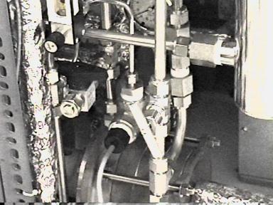
Figure 6: Water Drain
3. Connect a hose to the drain.
4. Put the other end of the hose in a bucket to catch the water.
5. Open the drain at the bottom of the system.
6. Run the water into a bucket.
7. Dispose of the water by emptying the bucket in a building drain.
8. The pump will automatically shut off when the water reaches the optical level sensor on the main pressure vessel.
9. This removes most of the water from the system.
10. The entire system will not run dry because many of the pipes do not point directly down.
11. It is not necessary to remove all the water in the system.
12. Refill the main pressure vessel with DI water from the Milli-Q Dispenser in the cal-station area.

Figure 7: Refilling DI Water>
13. Connect the hose to the DI "water in" valve on the top of the main tank.
14. Open the valve on top of the main tank, then open the valve above the tank, in the DI water line. (See Figure 7)
15. As soon as the tank fills, switch at the main panel on the pump and continue to fill the system with water.
16. At this time, the top lid is still off the pressure vessel. Fill with DI water to the top weld on the main pressure vessel.
17. Secure the top lid by screwing the black triangular handle clockwise until it is hand tight. (See Figure 7)
3.6 UV Jacket Function and Replacement
The quartz jacket looks like a large test tube. It holds the UV lamp inside and seals the water away from the lamp. Water flows through the sterilizer around the outside of the quartz jacket.
Replace the jackets when they look cloudy. Check the quartz jacket when replacing lamps 1 & 2. Always wear latex gloves when handling the UV jackets because finger oil transferred to the UV jackets will contaminate them.
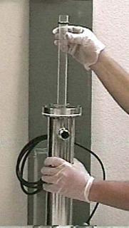
Figure 8: UV Jacket Pulled From Sterilizer (For demonstration purposed the sterilizer is not mounted on the cal-station.)
1. UV Jacket is immersed in the water.
2. Flip down switches 1, 2, and 3 at the main panel to turn off the power to the UV lamps.
3. Shut off the water flow to UV lamps by shutting off the main pump.
4. Or shut off the entire station by hitting the emergency stop button.
5. The threaded top metal piece holds the O-ring with a washer sitting around the top of the UV jacket. The top end receives an O-ring and a washer that holds the O-ring in place.
6. Undo the threaded top metal piece and the UV jacket will pop up out of the water.
7. If the UV jacket does not pop out of the water, gently wiggle the jacket to loosen it.
8. Replace the O-ring and the washer, and slide the new UV jacket back in place.
Note: There is a small jacket centering cup and spring at the bottom of the sterilizer columns. Place the bottom of the jacket in the centering cup. View the cup through the end of the jacket by using a flashlight pointed down inside the sterilizer.
9. Retighten the threaded top metal lid. Twist lid in place, finger tight.
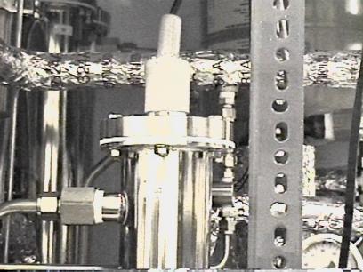
Figure 9: UV Lamp Sterilizer
3.7 Ultraviolet (UV) Lamp Function
There are 3 UV lamps in the cal-station which function as the DI water sterilization system. The lamps are mounted down inside the UV sterilizer. The UV sterilizers are stainless steel cylinders, approximately 36 inches high, and 3 inches in diameter. The lamps look similar to fluorescent lamps except
there are terminals on one end only. The lamps are ionizing lamps. The wavelength of these lamps is 185 nanometers (nM).
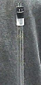
Figure 10: UV Lamp
The lamps light rays break apart water contaminants into ions then the DI canisters and filter canister will remove the contaminants. Replace lamps when the TOC test readings dont go below 1 ppb. Replace lamps when they show burn marks and look spotty.
Lamps 1, 2 and 3 are Ultradynamics brand (also known as Glasco), 120 volts. Lamps 1, 2 and 3 use a ballast.
WARNING!
UV light can damage the eyes. Do not look at the UV lamps when they are on. If the lamps need to be examined when turned on, be sure to wear UV blocking goggles.
3.7.1 UV Lamp Replacement
Wear latex gloves when changing the lamps because finger oil transferred to the lamp surface will cause the lamps to fail. If ungloved fingers touch the lamps accidentally, clean up the finger prints with isopropyl alcohol and clean wipes.
The lamps can be changed with the cal-station water running.
1. Turn off the power by unplugging at the receptacle in the power bay.
2. Pull up the gray strain relief. This strain relief holds the lamp off the bottom of the quartz jacket.
3. Gently pull up on the electrical terminals to disconnect them from the top of the lamp.
4. Pull the lamp out of the quartz jacket.
Note: Be careful not to drop the lamp, or it will shatter the quartz jacket bottom.
5.Gently lower the new lamp in the quartz jacket.
6. Plug in the electrical terminals at the top of the lamp.
7.Replace the gray strain relief.
Note: Wear latex gloves see above "UV lamps #1 & #2 Replacement" for reason.
3.8 Filter Function and Replacement
The filter catches DI particles or any other solid impurities in the water. The filter is replaced as needed. To replace the filter the cal-station needs to be turned off, or the filter needs to be isolated from the system by closing off the ball valves. If the filter is not effective, the particles in the water will plug the inlet screens on the test unit and interfere with its solenoid valve.
WARNING!
METHANOL IS POISONOUS, USE WITH CARE, do not to get any on your skin or splash any in your eyes.
Wearing latex gloves and safety glasses follow steps 1. through 12. below to change the filter.
3.9 Heat Exchange Function
A separate temperature control loop using a heat exchanger indirectly regulates DI water process temperature. The temperature range is between 20?to 70?C. Cooling is via a water chiller. Heating is via a 2 gallon 1.5 KW water heater. Distilled water/propylene glycol is pumped through the temperature control loop. Direct DI process water temperature sensing and control is sensed with a platinum RTD sensor and P.I.D. controller. A computer provides control over P.I.D. controller functions. (P stands for Proportional Band, I stands for Integral Time, D stands for Derivative Time, all measured by the Yokagawa Temperature Controller.) RTD stands for Resistive Temperature Device. Both items are components of the Yokagawa Temperature Controller System. They work together to control hot and cold temperatures desired.
Read the normal pressure of 40 PSI on the pressure gauge located at the top of the cal-station near the heat exchange loop. Glycol solution flows through the heat exchange loop. If the pressure is less than 40 PSI on the top gauge, this is an indication of pressure loss on the heat exchange loop.
The Yokagawa temperature controller regulates the three-way chiller solenoid valve. The solenoid valve controls cold water from the chiller. Cold water in the storage tank is isolated from the heat exchange loop by the solenoid valve. The water flow is at 2.5 GPM when isolated from the chiller. The water flow is at 1.5 GPM when running through the chiller. If the spring valve in the normally open solenoid breaks, there is no circulation of the glycol solution.
3.10 Repressurize the Heat Exchange Loops
The temp loop system sometimes leaks from around the fittings because of the heating and cooling of the glycol. Tighten the fittings on the temp loop system before re-pressurizing it.
The glycol solution is changed as needed, or once every year. If a chiller breaks, drain the system and repair or replace the chiller. Then refill the heat exchange loops with the same or new glycol solution, depending on the age of the glycol solution. Use a designated pressure pot filled with a solution of 10% glycol 90% water to repressurize the loops. Measure the concentration of the glycol solution with a refractometer, obtained from manufacturing engineering.
1. Fill pressure pot completely full of glycol solution.
2. Put the lid on by placing the lid with the gasket inside the can opening and pushing the lever down on the top of the can which pulls the lid up. (See Figure 11)
3. Close the pressure release valve located on the top of the lid.
4. Pressurize to 40 PSI with nitrogen by connecting a hose from the in port to the nitrogen tank stored near the cal-station.
5. Connect the hose from the pressure pot to the temp loop inlet on the cal-station.
6. Attach hoses to bleed the valve on top of the chiller. Second bleed valve is under the captive air expansion tank. Run hoses into two buckets. (See Figure 12)
7. Start with one valve closed.
8. Valves on top bleed off air and with the air some glycol solution.
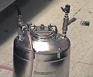
Figure 11: Close Up of Glycol Pressure Pot
9. Lift up the black 2 position valve on the top of the glycol out port and the pressure will push the glycol up into the system.
10. There are two temp loop purge valves. One is attatched to the top of the water heater and one is in the piping above the hot water heater. Open and close the temp loop purge valves until all air is purged from the system and all glycol is replaced.
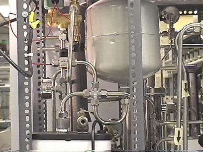
Figure 12: Temp Loop System
11. All the air is purged when the glycol runs clear with out any air bubbles in the line.
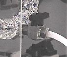
Figure 13: Glycol Inlet Valve On Cal-Station
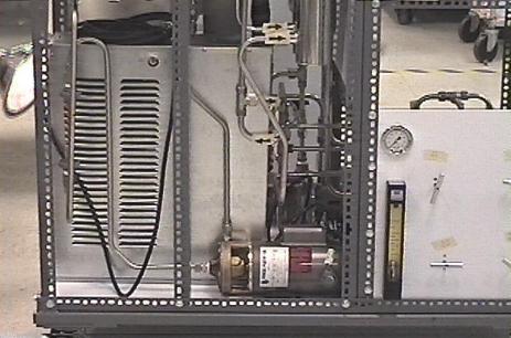
Figure 14: Chiller and Temperature Loop System
3.11 Chiller Operation
This section explains how the chiller operates, and gives an overview of the major components.
The pump draws water from the water tank, pumps it through the evaporator and returns it to the tank.
When the temperature control calls for cooling, the compressor is started. Liquid refrigerant flows from the expansion valve to the evaporator, evaporating and absorbing heat. The refrigerant gas flows to the compressor and condensing coil where it is cooled and returned to a liquid and the cycle repeats.
To prevent scaling and deposits use distilled water. If glycol is required we recommend propylene glycol (not more than 10%).
If the pump will no longer give sufficient flow or pressure, it must be replaced. Close the valves at the input and out flow of the pump before taking the pump out of line.
The noise coming from the pump will also change if it is in need of replacement. Sometimes this happens before the flow and pressure have changed substantially. Keep this in mind if you notice something strange in the pump sound.
3.12 Station Cleaning
Wipe down the white surfaces with a mild cleaning solution when they appear dirty. Wipe down the unit shelves between every production test batch.
3.13 Injection Port Repair
If the injection port starts to leak, turn off the two switches on the main panel marked Inj and Inj SV. Then unscrew the outer nut (not just the needle guide, but the large stainless nut) from the injection port. A green septa will either come off with it, or be stuck on the end of the threaded fitting. Remove this old septa, and replace with a new one.
Tighten the nut with your fingers only, open the valve again, and turn the switches back on. If there is slight leakage, tighten the nut up to 1/4 of a turn with a wrench. If there is a major leakage, take it apart again and inspect it. The septa should be mounted evenly to work.
3.14 Tank Cleaning
Small pieces of material may get into the tank on occasion. The tank should be inspected once a month and cleaned if necessary. The water in the system should be replaced at least once a month. Empty the tank as detailed in the startup document, and clean the tank by wiping. Use a clean cloth or paper towels. Use cleanroom wipes which are made from a particle free cotton fiber, if they are available.
4.0 Calibration Station Software
4.1 Introduction
The calibration station (cal-station) software checks the Taiwan Hallmark TOC monitors using four tests; background cleanliness, oxidation rate, TOC check and conductivity. The software captures readings from the instrument and compares them to readings from a reference instrument to produce a TOC certification and a Conductivity certification. The home page menu shown below lists choices available during a test cycle. The following text describes each button in detail. Access each destination by moving the mouse and clicking on the square button. The cal-station can be controlled from a remote server located anywhere in the world through a modem, an Intranet or Internet connection.

Figure 15: Home Page Menu
Description of Software Function
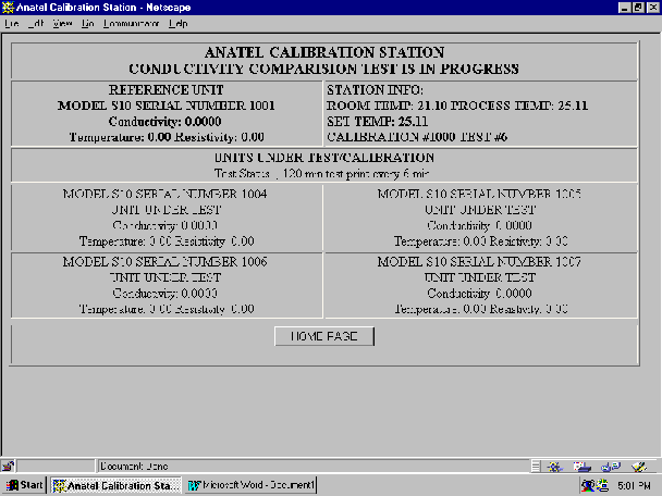
Figure 16: Clean Mode
4.2 Description of Software Function Background Test:
The Background Test determines if the instrument cell is contaminated with TOCs. A contaminated cell will produce invalid TOC results in normal operation and make calibration impossible or inaccurate. The Background Test will take one hour. This test is run with the station at very low TOC values < 2.0 ppb. Two results are produced. The first number is with the UV lamp turned off (Dark Phase Valve). The second number is with the UV lamp turned on (Light Phase Valve). The Dark Phase should be below 2 and the Light Phase should be below 10. Compare these numbers to an appropriate reference number for the instrument. These numbers should be within 10% of the reference numbers.
See Figure 17.
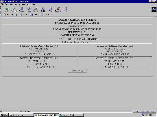
Figure 17: Background Check
4.3 Description of Software Function Oxidation Rate:
The Oxidation Rate test checks for validity and condition of the UV lamp.
See Figure 18.
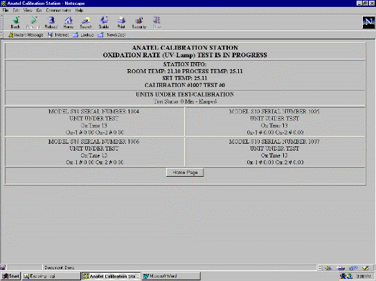
Figure 18: Oxidation Rate
The Lamp Test shows if the lamp intensity has decayed to a level where the oxidation process takes too long. Even a very old UV lamp may still produce valid numbers, but an old lamp increases oxidation time. The Lamp Test is a method of determining the condition of the lamp. The Lamp Test takes 30 minutes.
Oxidation Rate, cont?.
Lamp Test produces 3 numbers, ox time, ox1 number, and rate of change number
Ox time is the time it takes to oxidize a sample.
Ox1 indicates lamp condition. Rate of change indicates lamp start up time condition.
Ox times for an instrument are compared to an appropriate reference and should be close, within x.x% or x.x% of the normal readings.
As the UV lamp ages these numbers will increase.
When these numbers increase and rise x.x% or greater than the reference it indicates the UV lamp has deteriorated.
The ox 1 number should also be within x.x% to x.x% of the reference unit number and indicates the condition of the lamp. The rate of change should be within x.x% of the reference.
4.4 Description of Software Function Conductivity Check:
The Conductivity (Cond.) Check is used extensively for calibration and calibration verification. Unlike the other tests, the UV light of the instrument is not present during this test. Because of this feature, the conductivity test is a good indicator of temperature problems that might be caused by a leaky instrument cell, or other hardware failure. The Conductivity Check is another test run to check and validate the precision of the instrument. See Figure 19.
The conductivity test measures the conductivity of the water flowing through the cell.
Resistivity, temperature and conductivity numbers produced by this test should match the reference numbers for the instrument.
Instruments that measure outside the instrument specification will be highlighted in gray.
The conductivity check routine is a two-hour test.
Figure 19: Conductivity Check
4.5 Description of Software Function TOC Check:
The TOC Check uses the TOC algorithm defined by the instrument? firmware to check the instrument reading against a reference.
The TOC Check is used to quickly validate how well the instrument is performing.
A short, two hour TOC test is run. The instrument is injected to 1000 ppb and is allowed to very quickly clean up to 2 ppb, within 1 to 2 hours.
The instrument takes about ten readings in this period and compares them to the reference, and prints out a report. If the instrument is in good condition and performing correctly these numbers should match the reference within the instrument specifications.
Figure 20: TOC Check
These four tests indicate the instrument is functioning properly without any errors. Any error messages displayed on the report generation indicates instrument errors.
4.6 Description of Software Function TOC Cert.:
The TOC certificate routine produces a certificate of calibration for the instrument.
The test takes about 10 hours because the test requires a very controlled TOC ramp from under 1 ppb to 1100 ppb.
If the test runs through this program correctly it generates a report that indicates whether instruments have passed or failed.
The operator can then print out or display an actual certificate of calibration.
Since the test takes 10 hours it is important that the cal-station be set up correctly before beginning the test.
Any malfunction of the instrument or the cal-station will invalidate the test.
First make sure the cal-station is at a low < 2 ppb by placing the instruments into clean mode and allowing them to clean up for a minimum of 4 hours, it may take longer, depending on the condition of the instruments or the cal-station.
A short TOC check routine can be run to check what value the station is at.
The injectors should be checked to make sure it has enough methanol to perform the test.
4.7 Description of Software Function Conductivity Cert.:
Conductivity Certificate (Cond. Cert.) click mouse on the square button to create a certificate. See Figure 15.
This feature will be released at a later date.
4.8 Description of Software Function Add/Delete:
Add/Delete Test click mouse on the square button to display test status queue. See Figure 15.
Check the test you wish to add to the test queue and/or check the tests you wish to delete from the test queue. Enter special test using the manual test command line. These tests must conform to the manual test command set, see Table 1. Press the SEND Button to Submit the Selections to the test program. The program will display your changes. Press the HOME PAGE button to cancel the menu selections and return to the HOME PAGE. If you delete the first test in the delete test list the current test will be stopped.
Figure 21: Add/Delete
Description of manual test commands: enter commands on the blank line under manual test commands. These commands must conform to the command set in Table 1.
4.9 Export Cal-Station Software Manual Commands
Manual test command set. See Figure 24 "Manual Test Command".
FORMAT
When entering a command line, the format looks like this:
XXn:n XXn:n XXn:n *YY ZZn:n ZZn:n
Where XXn:n represents a process command, the n:n may be optional parameters depending on the command. The YY is a test (*BR *RT *T1 or *C1). The ZZn:n are options to the *YY test command.
The following commands are valid.
Table 1
|
TMn |
Set Time Out: limit to ??minutes defaults to 240 minutes or 4.0 hours. This is used by other commands that try to reach some set point but must time out if they fail to reach the set point. | |
|
TRn:n:n |
Temperature (temp) Ramp Command: the first ??is a time delay before starting the ramp. The next??is the final ramp temp, and the last ??is the ramp rate in deg/min. Maximum deg/min. = 0.4. If ramp rate = 0 then temp will step to ramp temp | |
|
TPn |
Temp Point Command: select the desired temp of the cal-station, 10 to 99 degrees C. | |
|
SPn |
Select Set Point: select the desired temp set point. The Temp Controller on the cal-station has 7 stored set points. This command selects the set point ??for 1 to 7. | |
|
TCn |
Wait for TOC: wait for the station TOC to reach ??before continuing with the test. If station does not reach ??in 240 minutes it will time out and continue the test. The time out limit can be changed with the TMn command. | |
|
TL |
Temp Lock: wait for the cal-station to reach room temp and lock. If the station fails to reach the room temp in 240 minutes it will time out and continue the test. This time out limit can be changed with the TMn command. | |
|
RP |
Reference Purge: put the reference unit, if it exists, in Purge mode. | |
|
RA |
Reference Analyze: put the reference unit, if it exists, in Analysis mode. | |
|
RC |
Reference Clean: put the reference unit, if it exists, in Clean mode. | |
|
RSn |
Wait for Resistivity: wait for the cal-station resistivity to reach ?? and then continue the test. If the station fails to reach the desired resistivity in 240 it will time out and continue. Change the time out limit with the TMn command. | |
|
HRn |
Select Mode: set all units to fast mode if ??equals 1 and to normal mode if ??equals 0. | |
|
HVn |
Select High Voltage: set all units to high voltage clean mode if ?? equals 1 and to high voltage clean mode off if ??equals 0. | |
|
DIn |
DI Cartridge: if ??1 DI can is inline if ??0 DI can is offline. | |
|
FLn |
Filter: if ??1 Filter is inline if ??0 filter is offline. | |
|
Ijn |
Injector ON/OFF: turn on the injector for ??seconds. | |
|
C0n |
C02 Valve ON/OFF: turn on the C02 valve for ?? seconds. | |
|
UVn:n |
UV Lamp ON/OFF: turn on UV lamp number ??if ??is 1. Turn off UV ?? if n equals 0. | |
|
UNn |
Units ON/OFF: turn on all UUT if ??=1. Turn off all UUT if ??0. | |
|
OXn |
Oxygen Valve ON/OFF: turn on the Oxygen valve for ?? seconds. | |
|
NVn1:n2 |
Set needle valves DI and UV to % open n1=UV% and n2=DI% | |
|
UP |
Units to Purge: set all UUT to the Purge mode. | |
|
UA |
Units to Analyze: set all UUT to the Analysis mode. | |
|
UC |
Units to Clean: set all UUT to the CLEAN mode. | |
|
WTn |
Wait: ??minutes before continuing the test. | |
|
ITn |
Set Fill Time: change the fill time for all UUT to ?? | |
|
*BR |
Run Background test. | |
|
*RT |
Run Real Time test | |
|
*C1 *C2 |
Run Conductivity test. Example *C1 LT600 IN5 | |
|
LTn Option to C1 command Set ??length of test in minutes. | ||
|
INn Option to C1 command Set ??number of samples per test point. | ||
|
*T1 *T2 |
Run TOC test. The following commands are options for the T1 command. Example *T1 TI14402 IJ90:1 | |
|
TNn Option for T1 command Set number of TOC test to run. | ||
|
T1 Option for T1 command Set length of TOC test in minutes | ||
|
TL Option for T1 command Set TOC limit. When limit is reached, stop test. | ||
|
IJn:n Option for T1 command Turn on the injector for ??microliters after ??th sample. | ||
|
SPn1:n2 |
Set temp to n1 after n2 sample has been taken. | |
|
Time Date Wait Command | ||
|
TD |
TDXX:YY:ZZ:AA:BB:CCCC | |
|
YY |
Min | |
|
ZZ |
Hour | |
|
AA |
Day | |
|
BB |
Month | |
|
CCCC |
Year | |
4.10 Description of Software Function Auto Calibrate Test:
Click mouse on the auto calibration square button to run the auto calibration program. This program runs the unit through a standard test sequence.
The Auto Calibrate routine begins by placing the cal-station in clean mode.
The Auto Calibrate routine cleans up the water to less than 2 ppb.
The Auto Calibrate routine brings the station resistivity to 18 meg ohms.
When the station reaches 18 meg ohms, a 30 minute test measuring conductivity will begin. At completion of 1.5 hour test, the station resistivity is lowered to 2 meg ohms, allowed to stabilize, then another 1.5 hour test at 2 meg ohm is run. At completion of the 18 and 2 meg ohm tests, the units are calibrated and a calibration report is displayed. The calibration is verified by running a 1.5 hour conductivity test at 2.0 meg ohms and 18 meg ohms.
All tests are done automatically and after completion of the 6 hour test, a summary report prints original values of instruments, gain and offset numbers, and the final new calibrated gain and offset numbers.
At the completion of this, a new TOC Cert test can be run to check for the validation of the calibration.
Figure 22: Auto Calibrate
4.11 Description of Software Function Review Test Data:
Click mouse on the Review Test Data square button to review test data before certificate is produced. See Figure 15. This button shows a history of all tests run since the add unit button was pressed.
4.12 Description of Software Function Station Status:
Click Station Status to check test in progress. This function identifies tests being performed at this time. See Figure 23.
Check carefully that instruments being calibrated are registered with the serial number and model number and they say "unit under test". The calibration process can now begin.
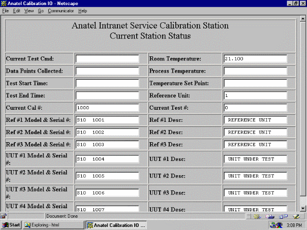
Figure 23: Station Status
4.13 Description of Software Function Add Units:
To start a calibration or verification, first install units on the station, then press the Add Units button. The system returns to the station status menu. Check that the unit model and serial # match the units installed. Any time a new unit is to be calibrated the add unit button must be pressed.
4.14 Description of Software Function Test Status:
The Test Status button is a convenient method to return to the current test being run. If no test is currently active, button returns to home page.
4.15 Description of Software Function Manual I/O Commands:
The Manual Commands push button located on the home page controls the operation of the cal-station in manual mode. The operator can press this menu button and an item will appear indicating the on/off state of the 12 I/O controls, UV1, UV2, UV3, DI canisters, filter, injector loop, injector, CO2 injection, external water injection, and 2 spares for future expansion. In addition to these controls there are automatic control valves which regulate how much water flows through the UV columns, This is the UV bypass and UV Flow valves. There is also a pair of ball valves on the DI canisters controlling how much water flows through the DI canisters. This allows a regulated control of the speed at which the station can clean up from a low meg ohm reading to a high meg ohm reading or the speed at which the station can clean up from a High TOC value to a low TOC value. Normally the manual controls are not used while automatic tests are in process. The manual command gives complete control of the station during all tests. Manual controls should not be used while automatic tests are in process unless doing a special test. See Figure 24.
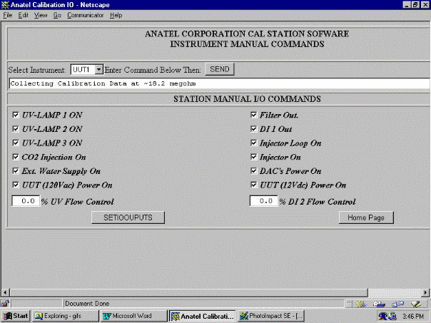
Figure 24: Manual Commands
4.16 Description of Software Function Temp Ctr (Control)
Temp Control sets up temperature control of water in system. See Figure 15.
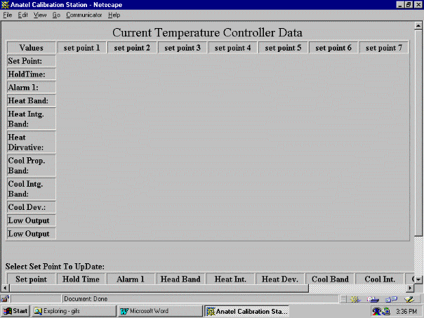
Figure 25: Temp Control
4.17 Description of Software Function Service Manual
Click the mouse on the Service Manual button to view on-line manual. See Figure 15.
4.18 Description of Software Function Anatel
Click mouse on the Anatel button to reach the Anatel Corporate Office on line. See Figure 15.
4.19 General Background Information
The Anatel cal-station is designed to calibrate and validate Anatel? A100, A10 and A1000 TOC instruments. The cal-station compares the test instrument to a known calibrated reference instrument. The cal-station has three references A1000, A100 and A10. Install the test instruments in positions 1, 2, 3, and 4 of the cal-station and connect the water lines and the communications cables to the test instruments.
The cal-station calibrates only one type of instrument at a time. The instrument placed in position 1 becomes the type of instrument to be calibrated. Any instruments installed that are not of the same type as 1, will default to clean mode and no data will be collected. The station selects a reference unit based on the test unit in position one.
Once the instruments are installed, click on "Add Units" icon of the home menu. After about 30 to 45 seconds the station status menu appears. This menu lists units on line, reference units, and units under calibration. This information must be correct before proceeding. Check carefully for instrument? registration with the serial number, model number and "on line" message.
The calibration process can now begin. The calibration consists of 7 steps: Background Test, Oxidation Rate, Conductivity check, TOC check, TOC Cert, Conductivity Cert, and if required, Auto Calibrate.
4.19.1 The syringe is an essential component of the cal-station.
The syringe is used to inject methanol into the cal-station to control levels of TOC?.
The computer controls the syringe.
The size of the syringe is 10 mm.
Roughly 100 ? will produce 1000 TOC in this cal-station.
Take care to fill the syringe correctly.
Fill the syringe, then remove all air bubbles from the syringe body and needle.
Place the syringe in the injector housing so there is no space between the lip of the syringe and the holding mechanism and push rod of the automatic injection device.
4.19.2 Anatel TOC Monitor? Test Procedure
1. Run the background test first. See Figure 15.
The background test checks the cleanliness of a unit. If the instrument is contaminated, then a calibration cannot be performed until the instrument is cleaned up.
2. Oxidation Rate is next test. See Figure 15.
Oxidation Rate test checks for validity and condition of the UV lamp.
3. Conductivity Check is next test. See Figure 15.
The Conductivity Check tests the resistivity and temperature measurement of the TOC monitor to make sure it measures the conductivity of the water correctly.
4. TOC check is next test. See Figure 15.
The TOC check validates the accuracy of the TOC monitor. The routine matches test unit specification with the reference unit specification to make sure the instrument is measuring the conductivity of the water and the TOC value correctly.
These four tests report if the instrument is functioning without any errors. If the test units are functional, then proceed. If not, fix the hardware problems.
5. Next perform the TOC Cert routine. See Figure 15.
TOC routine will attempt to produce a certificate of calibration. If the TOC cert program fails, and this will be indicated when test completes, run the calibration routine.
6. Next perform Conductivity Cert. See Figure 15.
The Conductivity Cert will attempt to produce a Conductivity Cert for the instrument. If the Conductivity Cert fails, calibrate the unit.
7. Auto Calibrate Routine See Figure 15.
Before running the calibration routine check the background, TOC Check, Conductivity Test and UV tests to insure there is nothing malfunctioning before proceeding with the calibration. Calibrations are generally unnecessary unless a major component is replaced or changed, or the stored calibration factors have been inadvertently lost. The Auto Calibrate routine begins by placing the cal-station in clean mode until the station water is less than 2.0 ppb and the station resistivity is 18 meg ohms. When the station reaches 18 meg ohms, a 1.5 hour test measuring conductivity will begin. At completion of 1.5 hour test, the station resistivity is lowered to 2 meg ohms, allowed to stabilize, then another 1.5 hour test at 2 meg ohm is run. At completion of the 2 meg ohm test, the station returns to 18 meg ohms and another 1.5 hour test runs. These three tests, two, 18 meg ohm tests and one 2 meg ohm test are used to calibrate the instrument. All tests are done automatically and after completion of the 4.5 hour test, a summary report prints original values of instruments, gain and offset numbers, and the final new calibrated gain and offset numbers.
Repeat steps, 3 Conductivity Check, 4 TOC Check, 5 Toc Cert., 6 Conductivity Cert., until valid certificate is produced.
At the completion of this, a new TOC Cert. and Conductivity Cert. can be run to produce the two Certificates of Calibration.
4.20 Review test data button See Figure 15.
At the beginning of the test cycle or at the completion of a single test, a report is generated. A summary of the test showing the results is stored in an HTML document that can be referenced through this push button.
Test status button returns to the current test. If no test is active the button returns to the home page.
View manual and view software manual push buttons display on line documentation of software and hardware manuals.